Connection II, Connection II IP and Connection III IP family of products provide microwave radio solutions to cellular backhaul and point-to-point access markets. The product line is available in ETSI (European) and ANSI (North American) standards.
Our product line covers the range from 3.5 GHz to 60 GHz frequency band in both ETSI (European) and ANSI (North American) standards. The Connection Series, which employs a continuous phase modulation (CPM) scheme to offer superior performance that is equal to or better than QAM or QPSK systems, at an FSK level cost.
State-of-the-art microwave radio solutions to both the mobility (cellular backhaul) and the access markets.
System Features
The Connection Series II™ Radio provides:
| Low Installation Cost (Single Outdoor Unit) |
| Programmable Capacities (1, 2, or 4E1) or (1, 2, or 4T1) |
| Robust Constant Envelope Modulation Scheme (Duo Quaternary Continuous Phase Modulation (DQCPM) |
| SNMP Management and Configuration via an optional Indoor UnitWireless Remote Unit for Monitoring and Control |
| Equipment Layout and Main Assemblies
|
The Connection Series II™ radio terminal consists of an Outdoor Unit (ODU), an antenna/ mounting assembly and an optional Indoor Unit (IDU).
Outdoor Unit
The outdoor unit contains the RF Assembly, the Processor Assembly, the RF Diplexer and the Modem/ Interface Assembly.

Overall Block Diagram of Connection Series II™ Radio
Outdoor Unit Signal Flow
Diplexer Assembly
The Diplexer consists of two waveguide filters, one each for the transmitter and the receiver. The function of the diplexer is to separate the transmitter and receiver signals and to provide adequate noise suppression of the Transmit from affecting the receiver. The diplexers are designed to be wideband and they are tailored to accommodate the various transmit to receive frequency separations (T/R spacings) as dictated by applicable specifications.
RF Assembly Description
The Transmitter Signal Path
The transmitter circuitry of the RF Assembly consists of a modulated, synthesized source operating at 1/8th to 1/16th of the RF output frequency, depending on the band. The analog data from the Modem Assembly are applied directly to the synthesized VCO. The output of the VCO is passed through a set of multipliers, filters and amplifiers to generate the desired frequency.
The Receive Signal Path
The received RF signal from the diplexer is amplified by the LNA and sub-harmonically converted to baseband I and Q signals. The I/Q signals are amplified and filtered by a set of baseband amplifiers whose gain is controlled by the AGC signal from the microprocessor.
The Antenna and Mount
AssemblyAn antenna and mounting assembly is supplied with the radio terminal. It is designed to attach the ODU to a pipe or cylindrical tower member having a diameter of 1.5 to 4.5 inches. The mount configuration also permits removal of the ODU without disturbing the antenna alignment. Various sizes of antennas are available and all can be accommodated by the same mount.
The mounting assembly provides three 30° elevation coarse adjustment increments for a total of 90 degrees of elevation adjustment range and two 45° azimuth coarse adjustment increments for a total of 90 degrees of azimuth adjustment range.
Typical Point-to-Point System

Typical 60GHz Radio System

Connection II Series Microwave Radios
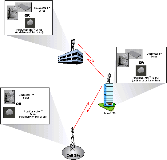
The primary application of this radio is to interconnect cellular base stations whereby the cellular traffic is generally aggregated into E1/T1 traffic streams.
This radio is offered in the following configurations:
Connection Series II™ Series Low Capacity (ETSI)
International Markets 3.5, 13, 15, 18, 23 & 38 GHz Microwave Radio – Low Capacity
Connection Series II™ Series Low Capacity (ANSI)
North American Markets – 15, 18, 23 & 38 GHz Microwave Radio - Low Capacity
Connection Series II™ Series Medium Capacity (ETSI)
International Markets – Medium Capacity - 3.5, 13, 15, 18, 23 & 38 GHz Microwave Radio
Connection Series II™ Series Medium Capacity (ANSI)
North American Markets – Medium Capacity - 15, 18, 23 & 38 GHz Microwave Radio
AirPair 11-38 GHz Ethernet
AirPair Applications
6-38 GHz FibeAir 1500 Family
60 GHz FibeAir 10060
FibeAir 4800 Family
FibeAir 3200T
FibeAir IP-MAX
60GHz Wireless Technology Overview
AR60/AR60X AdaptRate Gigabit Wireless Link
GE60/GE60X Gigabit Wireless Link
FE60/FE60X 100Mbps Wireless Link
GigaLink 6221/6421/6451
The Connection Series Radios are designed to support a variety of short-range applications that include:
Connection Series II™ (IP) Radio in the Access (Last Mile) Market
This radio can be used to provide point-to-point connectivity between the service provider Point-of-Presence (POP) and the customer premise.
Connection Series III (IP) Radio for IP Traffic Backhaul
The primary application of this radio is to interconnect cellular base stations whereby the cellular traffic is generally aggregated into E1/T1 traffic streams.


